Checking piston-to-valve clearance is an essential part of any engine build. In this tech installment, we show you how to do it.
Aggressive camshafts and high-compression ratios are necessary for maximum power in an engine, but they also create a very risky relationship between the valves and pistons. Basically, the two components can get too close to each other, and at high RPM any contact will result in some type of damage.

The trend towards boost has relaxed some of the anxiety among engine builders as the static compression ratios have decreased when compared to high-strung naturally aspirated engines. However, it’s still critical that the piston-to-valve clearance be checked during engine assembly—especially if there have been any changes to the engine that could affect this critical clearance. Examples include resurfacing the deck of the cylinder block or cylinder head, going to a thinner head gasket, increasing the ratio of the rocker arms or installing a high-lift camshaft.
Opinions may vary between piston and valve manufacturers, but a popular consensus is a minimum clearance of .080-inch for the intake and .100-inch for the exhaust. The exhaust valve expands more due to heat from combustion, and therefore needs additional clearance. If the engine is equipped with aluminum connecting rods, it’s usually a good idea to add .030-inch to the minimum clearance because aluminum expands more than steel. When the rod expands, the piston is shoved closer to the cylinder head.
There are two popular methods for checking clearance: the clay method and the dial-indicator method. This tutorial will focus on the latter as it is generally considered the more accurate of the two methods.
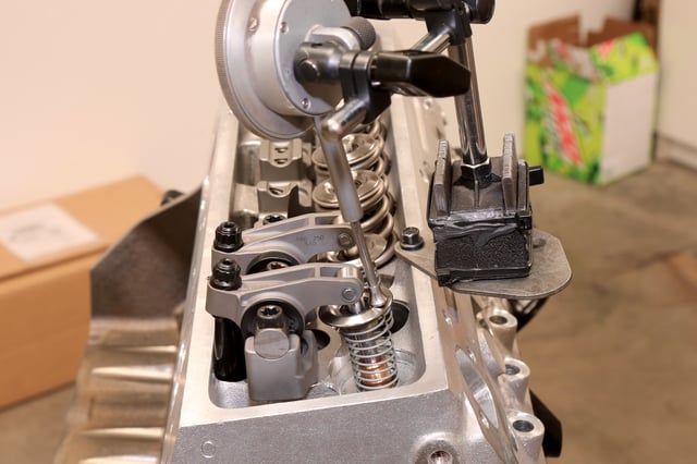
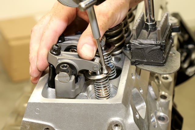
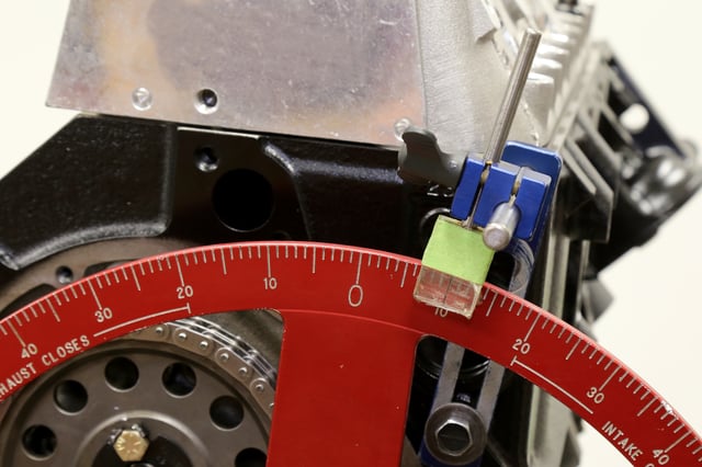
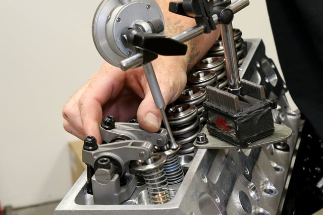
Required tools include a dial indicator and base, low-tension valve springs and a large timing wheel.
Following is a quick example of measuring piston-to-valve clearance as demonstrated by John Himley of CNC Motorsports in Brookings, South Dakota.
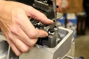
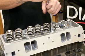
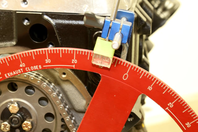 Rotate the crankshaft to 10 degrees before TDC on the exhaust stroke.